NDI - 3D Scan Transformation

General Description
A tool to model 3D objects starting from a 3D scanning source has been developed. More specifically, it makes the large output files usable for other systems, mainly focusing on anti-collision applications. This is achieved by applying a series of 3D data processing algorithms to simplify and convert to suitable format so that certain criteria (mostly fixed by the anti-collision applications) are fulfilled.
| Resource | Location |
|---|---|
| Repository Location | Link |
| Latest Release | Vs 1.0.2 |
| Open API Spec | Link |
| Video | Link |
| Further Guidance | None |
| Related Datasets | None |
| Additional Links | None |
| Generation date of this content | 30 May 2021 |
Screenshots
The following images are illustrative screen shots of the component

Figure 55. NDI - 3D Scan Transformation
Component Author(s)
| Company Name | ZDMP Acronym | Website | Logo |
|---|---|---|---|
| Ikerlan S. Coop. | IKER | www.ikerlan.es |  |
Commercial Information
| Resource | Location |
|---|---|
| IPR Link | Link |
| Price | [For determination at end of project] |
| Licence | [For determination at end of project] |
| Privacy Policy | [For determination at end of project] |
| Volume license | [For determination at end of project] |
Architecture Diagram
The following diagram shows the position of this component in the ZDMP architecture.

Figure 56. Position of component in ZDMP Architecture
Benefits
Use and management of 3D mesh files
Simplification of geometries for rapid deployment
Digitalisation and rendering of 3D objects
Features
The 3DScan component encapsulates mesh processing algorithms and seamlessly integrates them in the ZDMP platform. It uses the data management tools from the ZDMP environment and provides an easy-to-use API through which other components or zApps may use the embedded algorithms.
3DScan is divided in two different subcomponents, namely ObjectDefinition and CollisionDetector, to simplify existing mesh files to be used in an anti-collision system and evaluate prior to its usage potential collisions in the system.
The ObjectDefinition subcomponent offers the following features:
A conversion engine to clean, transform and reduce cloud of points to relevant simplified meshes
Parametrizable algorithms to be adapted to different geometries
Common mesh files (stl, ply, etc) can be simplified to the storage
Evaluation of the mesh metrics in order to evaluate the simplification result
The CollisionDetector subcomponent has the following features:
The end user can select different geometries for movable/non-movable parts in machine workspace
Movable parts are movable by means of keyboard input or by introducing a trajectory file
Potential collisions are detected in advance
System Requirements
All software dependencies are defined in the Dockerfile, so there is no need to specify them. As for hardware, output files of 3D scanning operations are quite heavy. They can easily size to 300 MB. That is why a minimum RAM memory of 8 GB is recommended.
| Software | Version |
|---|---|
| Docker | 19.03.13+ |
| Python | 3.8+ |
| Flask | 1.1.2 |
| Flask_Restx | 0.2.0 |
| Waitress | 1.4.4 |
| Requests | 2.25.0 |
| Hardware |
|---|
| 8GB+ RAM |
Associated ZDMP services
Required
Secure Authentication and Authorisation: Needed to secure the communication between components and authorize API calls
Portal: To access all services within the platform, centralizing the authentication procedure
Service and Message Bus: For the communication between the component and a zApp or another component
Application Runtime: To run the component within the platform ecosystem
Optional
- Storage: The Storage component stores data for later processing
Installation
To test the subcomponent(s), the next lines have to be run:
``` shell
cd orchestration
docker-compose -f 3dscan.docker-compose.yaml up -d --build
How to use
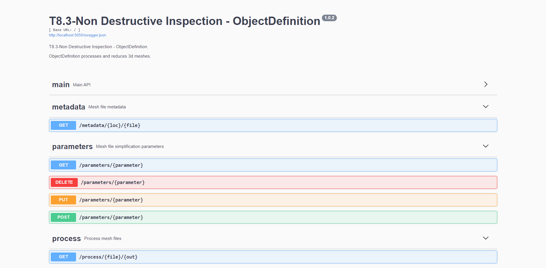
Once the Component has been built and started, the Developer can reach the Swagger Web UI at http://localhost:5050, assuming it is running on a local machine. At this URL, the developer can access the main APIs the ObjectDefinition backend mainly offers:

Figure 57. ObjectDefinition OpenAPI definition
Three main functions are available to use:
Metadata: obtain relevant metadata of the 3D object
Parameters: create, introduce, modify, and delete relevant parameters needed for the simplification algorithms to run
Processes: simplify the 3D object under the defined requirements
The ObjectDefinition backend is integrated in a frontend that eases the usage and improves the user experience.

Figure 58. ObjectDefinition frontend
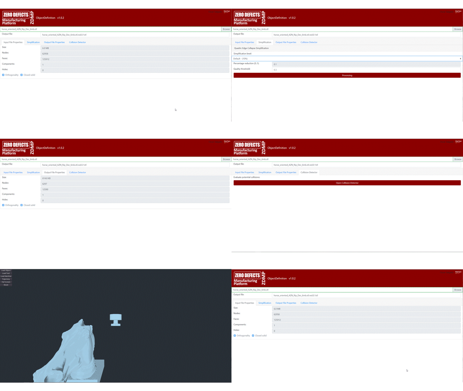
The usage of the component eases the transformation of the mesh files making it straightforward. Once a mesh file is selected (in the example below horse_oriented_AZN_Rip_DEC_6mb.stl) the frontend presents its main characteristics and metadata, such as the file size, number of nodes and faces, components, and holes, along with checking different properties such as the orthogonality of existing faces and that the mesh is a closed solid.

Figure 59. Input file loading and metadata extraction
Next, the user may need to simplify the introduced file, looking for a file that while maintaining main geometric characteristics results in a reduced size file. The frontend offers a simplified UI that allows the selection of the simplification level that the user requires.


Figure 60. Simplification parameters selection
After that, and once the output filename has been defined, a simplified (reduced) mesh is obtained, being the new metadata presented by the frontend.

Figure 61. Output file metadata
The Collision Detector component has been developed using Godot and it can be accessed at http://localhost:8765/CD.html. It allows evaluating the potential collision between components in a machine tool chamber. Currently, it is possible to change and adapt geometries, test potential collisions either by introducing a keyboard input or by introducing a trajectory input file.
To ease the usage and interaction with the Collision Detector component, the Object Definition frontend redirects the user to the former direction, allowing to directly test initial and simplified geometries.

Figure 62. Collision detector access
Once opened the Collision Detector interface makes possible to test different possibilities, namely:
Select different geometries of the Object – geometry to be machined
Select different geometries of the Tool – machining component
Select different geometries of the Machine – machine workspace
Introduce a trajectory for the machining process – trajectory
Apart from the previous options, the user can also use the component in full screen mode and reset to a normal screen mode.

Figure 63. CollisionDetector UI

Figure 64. Options available in the CollisionDetector UI